VIMethodology
- Author
- Leonardo Pinero-Perez
- Written
- 2018 · Report, University of Texas at Arlington
- Original
- Full report · 120 pages
- Contents
- Nomenclature · Chapter I · II · III · IV · V · VI · VII · VIII · IX · X · XI · Appendix · References
- Ref
- MAE 4351-2018
Converted from the original PDF on with Claude Opus 5.5. The wording is unchanged, except: two classmates’ names are replaced by their roles, Figure 54 (an attendance sheet) is omitted, and my name is spelled without accents. Equations, figures and numbering follow the original. Conversion not yet checked against the PDF.
ADerivation of Methods
To build the team multidisciplinary analysis, the chief first talks with the disciplines to assess progress on their respective literature reviews. From this, the methods which require inputs from others come into view. A synthesis discipline meeting determined the flight phases to be examined within the design-critical mission. These identified some design drivers (focused on the hypersonic vehicle) which would influence the team MDA and IDA’s. The flight phases examined are as follows:
- Launch Pad
- Structures: stationary load case
- Synthesis: weight pressure on interface with rocket stage (launch team structural load case)
- Launch
- Performance: obtain trajectory from launch team
- Structures: load case for maximum dynamic pressure
- Controls: neutral point and moment contributions to overall vehicle
- Engine Burn in Space
- High thrust for more efficient orbital maneuvers
- Controls: keep spacecraft pointed in the right direction
- Performance: insertion trajectory and trajectory beginning
- Operations in Space
- CAD: mission hardware, mass distribution, life support, etc.
- Controls: RCS performance
- Performance: orbit decay, trajectory visualization
- Propulsion: engine restart capability
- Structures: radiation protection (heating), pressurized vessel
- Atmospheric Inclination Change
- Controls: hypersonic stability at vehicle orientation, RCS usage, control surface sizing
- Performance: time to turn, periapsis, trajectory change, energy loss and delta V required
- Aerodynamics: aerodynamic properties during hypersonic turn
- Structures: TPS required for phase
- Final Re-entry from Orbit
- Structures: TPS with empty weight
- Performance: trajectory based on aerodynamic variables, keep track of cross-range
- Controls: stability across all speed regimes
- Aerodynamics: flight variables for all speed regimes and angle of attack
- Subsonic Approach
- Performance: meeting field requirements
- CAD: determine how a switchblade wing would fit and mechanized
- Control: stability and control sizing for approach and landing
- Aerodynamics: subsonic flight variables
- Landing and Ground Roll
- CAD: landing gear
- Performance: landing
- Structures: empty weight-on-wheels load case
BDiscipline Inputs and Outputs
The following is a compilation of inputs and outputs written by each discipline, used to derive a reasonable MDA based on each team members’ literature review.
Synthesis [29]:
Relevant Flight Phases:
- Launch Pad
- Launch
- Engine Burn in Space
- Operations in Space
- Atmospheric Inclination Change
- Final Re-entry from Orbit
- Subsonic Approach
- Landing and Ground Roll
Inputs:
- Mission Requirements (Chief Engineer, Synthesis and Performance)
- Propulsion Parameters
- Isp values, Mass Ratios for different flight maneuvers and phases
- Aerodynamic Coefficients (Aerodynamics)
- Coefficient of lift/drag values at different altitudes and different Mach Number
Outputs:
- Market and Orbit Analysis (to come up with mission requirements)
- Max Take off gross weight
- Generic Weight Sizing
- Max Take-off weight
- Fuel weight
- Empty weight
- Wing Loading
- Thrust Loading
- Generic Volumetric Sizing
- Length
- Width
- Height
- Scaling Factor due to a change in mission requirements
Methods:
- Methods
- Hypersonic Convergence
- Cszyz Method
Performance [15]: IDA Construction: The performance team’s IDA is structured around verification of the Model 176’s capabilities by performing an analysis of four distinct flight phases using data provided by other teams. These four flight phases are vacuum operations, aerodynamic orbital maneuvering, re-entry, and low-speed landing. As each phase has considerably different requirements and occurs in drastically different environments, four separate analysis methods must be performed. Each method will determine the capabilities of the vehicle during those specific flight phases, and the calculated trajectories (with variables such as Mach number, altitude, and peak vehicle temperature as functions of time) will be used as outputs to various teams. Additionally, the vehicle’s capabilities as found by these analyses will be compared to a provided set of mission requirements to ensure that they are possible.
Relevant Flight Phases:
- Engine Burn in Space
- Atmospheric Inclination Change
- Final Re-entry from Orbit
- Subsonic Approach
- Landing and Ground Roll
Inputs:
- Aero: drag polar, ,
- Thermal: at nose (sanity check), max total heat absorbed (if applicable)
- Structures: full/no fuel weight (), load factor limits
- Propulsion: max engine thrust,
- Synthesis: mission requirements (desired orbit characteristics, required orbital maneuverability, reentry cross range capability and desired load factor)
- Rocket Team (trajectory): flight condition post separation from Falcon
Outputs:
- To Aero(thermal):
- To Propulsion/Structures:
- To Synthesis: cross-range capability, max reentry load factor, trajectory optimization plots
Methods:
- Aerodynamic Plane Change: Minimum-Fuel Aerodynamic Orbital Plane Change Maneuvers by Joosten
- Important Variables: , desired inclination change,
- Re-entry: 1st order analysis described in Aerospace Vehicle Design by Corning
- Important Variables: ,
- Vacuum Maneuvers – Space Mission Analysis and Design by Larson and Wertz
- Important Variables: desired orbit characteristics, engine parameters, fuel weight available
- Low-Speed Landing – using code from previous semester to estimate landing speed and field length
- Important Variables: ,
Aerodynamics [16]:
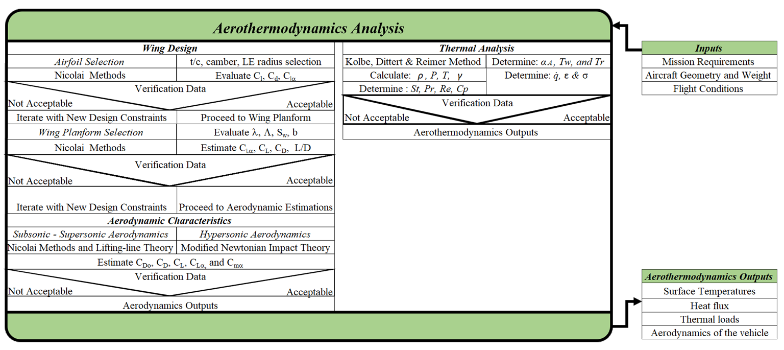
IDA Construction: Vehicle geometry, weight, and flight conditions are provided to the analytical tools. The results from the analysis will be validated using the database collected from the literature review. The validated tools will then be used to analyze and re-engineer Model-176. The results i.e. Aerodynamic Loads, Coefficients, and Stability Derivatives obtained from the analysis are provided to S&C and Structures. Output from this analysis as well as inputs from other disciplines become the inputs for TPS and its design. The convergence criteria lie in the thermal and structural properties of the material used.
Relevant Flight Phases:
- Operations in Space: L/D, Atmospheric Conditions, Geometry, Weight
- Atmospheric Inclination Change: L/D, Atmospheric Conditions, Geometry, Weight
- Final Re-entry from Orbit: L/D, Atmospheric Conditions, Geometry, Weight
- Subsonic Approach: Lift, Drag, Weight
- Landing and Ground Roll: Lift, Drag, Weight
Inputs:
- CAD: Aircraft Geometry
- Synthesis/Structure: Weight, Volume
Outputs:
- S&C: Aerodynamic Coefficients, Stability Derivatives (CL, CM, etc.)
- Structures: Aerodynamics Loads
Methods:
- Wing Planform & Airfoil Selection: Aircraft Weight, Geometry, Flight Conditions (i.e. Landing)
- Drag Estimations: Geometry, Flight Conditions
- Aerodynamics Characteristics: Geometry, Flight Conditions
- ANALYTICAL DETERMINATION OF THE THERMAL LOADS by Anna Kolbe (Technical paper)
- Elements of Spacecraft Design: by Charles Brown
- Design Methods for Space Transportation
Stability and Control [19]:
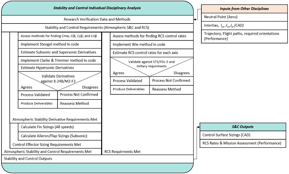
IDA Construction: The major factors in building the S&C IDA was to determine what flight phases require unique methods to investigate. Through literature search it was determined that there are 4 major regimes that methods must be made for. Orbital RCS, Hypersonic, Supersonic, and Subsonic flight phases. The primary derivatives listed are the major variables to determine stability on a conceptual level. Control sizing has to be assessed at different critical flight phases and of interest are conditions with the lowest dynamic pressure due to a lack of control power and where the most elevator control power is needed at landing.
Relevant Flight Phases:
- Engine Burn in Space: What can be done if engine isn’t perfectly center
- Operations in Space: RCS rates and requirements
- Atmospheric Inclination Change: Max bank and angle of attacks, low dynamic pressure control sizing
- Final Re-entry from Orbit: Low dynamic pressure control sizing
- Subsonic Approach: Wing aileron sizing
- Landing and Ground Roll: Elevon sizing
Inputs:
- Mission Requirements (Trajectory and Flight Conditions) (Performance)
- CG and Inertias (W&B/CAD)
- CLα, Aero estimated Cmα, NP (Aero)
Outputs:
- Stability assessment (S&C Cmα Cyβ Cnβ Clβ estimated (Synthesis)
- Control surface requirements (CAD/Aero)
- RCS requirements (Locations, fuel required) (W&B/CAD)
Methods:
- Stengel Method (Geometry/aero input) (Subsonic/Supersonic)
- Clark and Trimmer Method (Geometry input) (Hypersonic)
- Phillips/Nicolai Method (Geometry input) (Air based control sizing)
- Wie Method (W/B input) (Orbital RCS sizing)
Propulsion:
IDA Construction: Design of rocket propulsion history for already built engines. Outputs of engines already made will be used to create the best efficient engine made. Weights of vehicle and engine volume will be needed inputs from other disciplines to size the engine for performance. Main outputs consist of specific impulse, thrust-to-weight ratio, mixture ratio, chamber pressure and velocity at exhaust.
Relevant Flight Phases:
- Engine Burn in Space: What can happen if engine doesn’t start.
- Operations in Space: RCS, OMS and Main Engine Burns for Mission Requirements.
- Atmospheric Inclination Change: RCS and OMS propulsion system
- Final Re-entry from Orbit: Engine with Max Thrust & least Propellant Consumption.
Inputs:
- Synthesis/Structure: Weight (W) for Thrust-to-Weight Ratio
- CAD: Engine Volume (VE)
Outputs:
- Performance: Thrust (T), Specific Impulse (Isp), Engine Weight (Wengine)
- Mix Ratio (MR) & Fuel Density
Methods:
- Modeling technique but also including historical modeling methodologies
- Engine Selection, Engine Weight, Flight Condition (Space)
- Excel & MATLAB
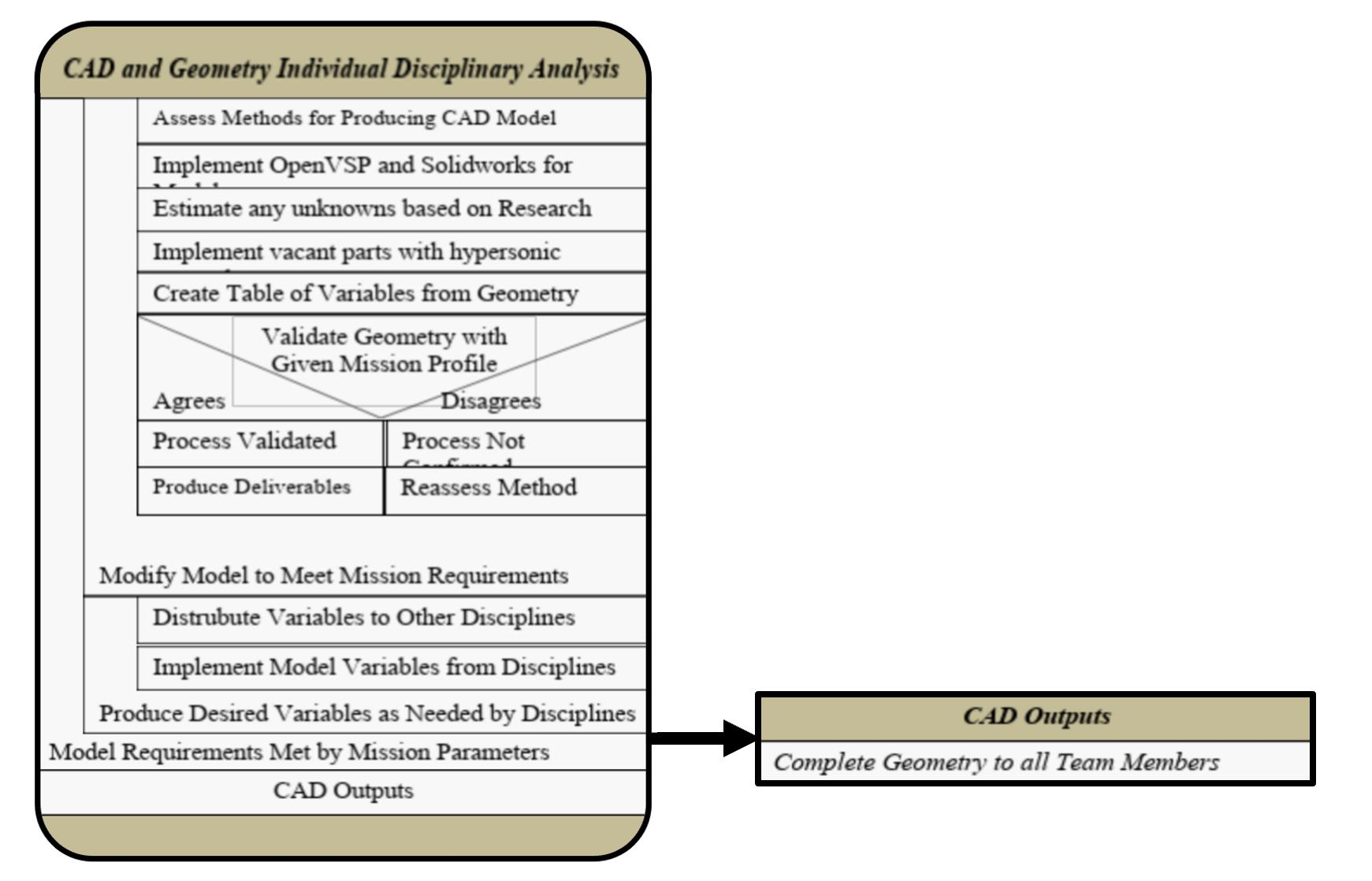
CAD [20]: IDA Construction: The CAD IDA was constructed by analyzing the necessary parameters to create the CAD models of the aircraft first. Then, determining which methods (software packages) were going to be used, before determining what is needed from the CAD discipline by other members of the team in order to finish their analysis. Finally, the deliverables were included as an output to the IDA, before adding the feedback iteration loop to demonstrate the nature of the process by which the model is refined. The IDA is simplified in that CAD as a discipline is largely independent of flight phases, with the exception of the wings being deployed at subsonic speed. This allows for a short and streamlined IDA which is easy to read and understand. Relevant Flight Phases:
- Engine Burn in Space
- Operations in Space
- Atmospheric Inclination Change
- Final Re-entry from Orbit
- Subsonic Approach
- Landing and Ground Roll
Inputs:
- Geometry from research
- Size and weight requirements based on propulsion and aerodynamic needs
Outputs:
- Geometric model to determine aerodynamic characteristics to aerodynamics
- Geometry and inertias to determine stability coefficients for stability and control
- CAD model for 3D print deliverable
- Visualization of the interior cabin of each iteration of the spacecraft
Methods:
- OpenVSP
- SolidWorks
CClass MDA
The following MDA was devised as a temporary placeholder for the first two weeks, based on the two sub-team MDA diagrams and inter-team communication.
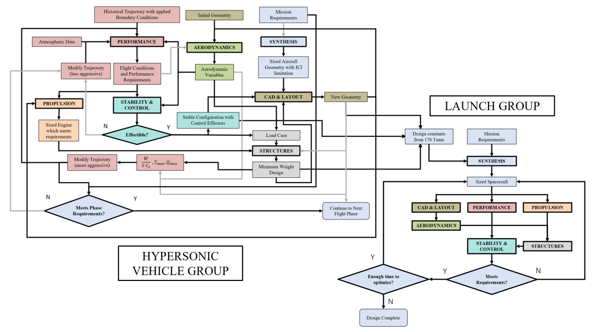
After presenting to Dr. Chudoba, the above preliminary class MDA was found to be in need of serious revision. The arrows were flowing in many directions and splitting off, and there was a clear need
The first version shows a simplified version of a Nassi-Schneiderman diagram. Within the class MDA, the two sub-teams will form their MDA’s to be iterated. The reason for having two levels of hierarchy is due to a premonition about iterating the sub-team MDA’s throughout the semester. In this way, the upper-level class MDA may remain constant with respect to set mission and MAE 4351 Capstone requirements while there is an allowance for sub-team iteration at the lower level of hierarchy.
The second version of the revision shows the previously simple class MDA in a more detailed way. Both versions are kept as the first version is useful for quick explanation of the class process.
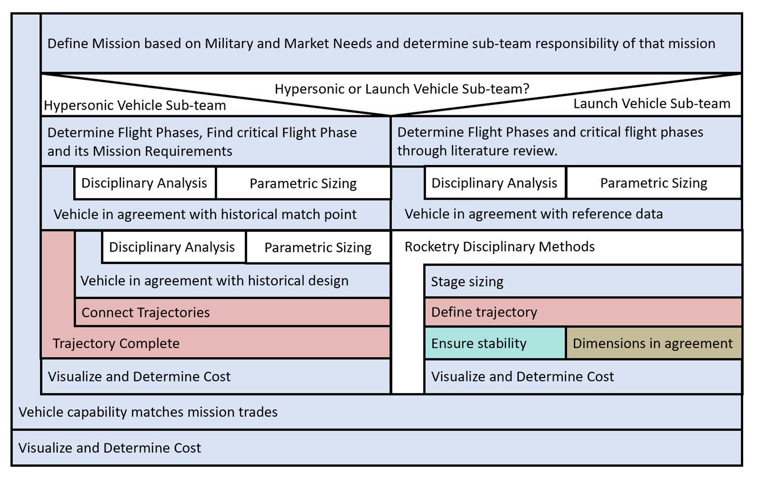
The class starts with the given mission profile and environment. This includes surface geography, launch sites, and last trajectory of the combined vehicle. With this last trajectory, the class can determine the domains of flight and analysis for each vehicle. This is where the teams split. Flight phases are then determined. The Hypersonic sub-team identifies the design critical flight phase and begins its disciplinary methods inside that loop. The hope is that most of the need for sub-team MDA iteration can be caught in this loop. The next loop continues through the next flight phases until the trajectory is complete. The large outer loop allows for mission trades and/or re-defining of domains (for example, that last known combined vehicle trajectory).
A more detailed look at the class MDA is shown below. Here the critical first step for the class can be examined more thoroughly.
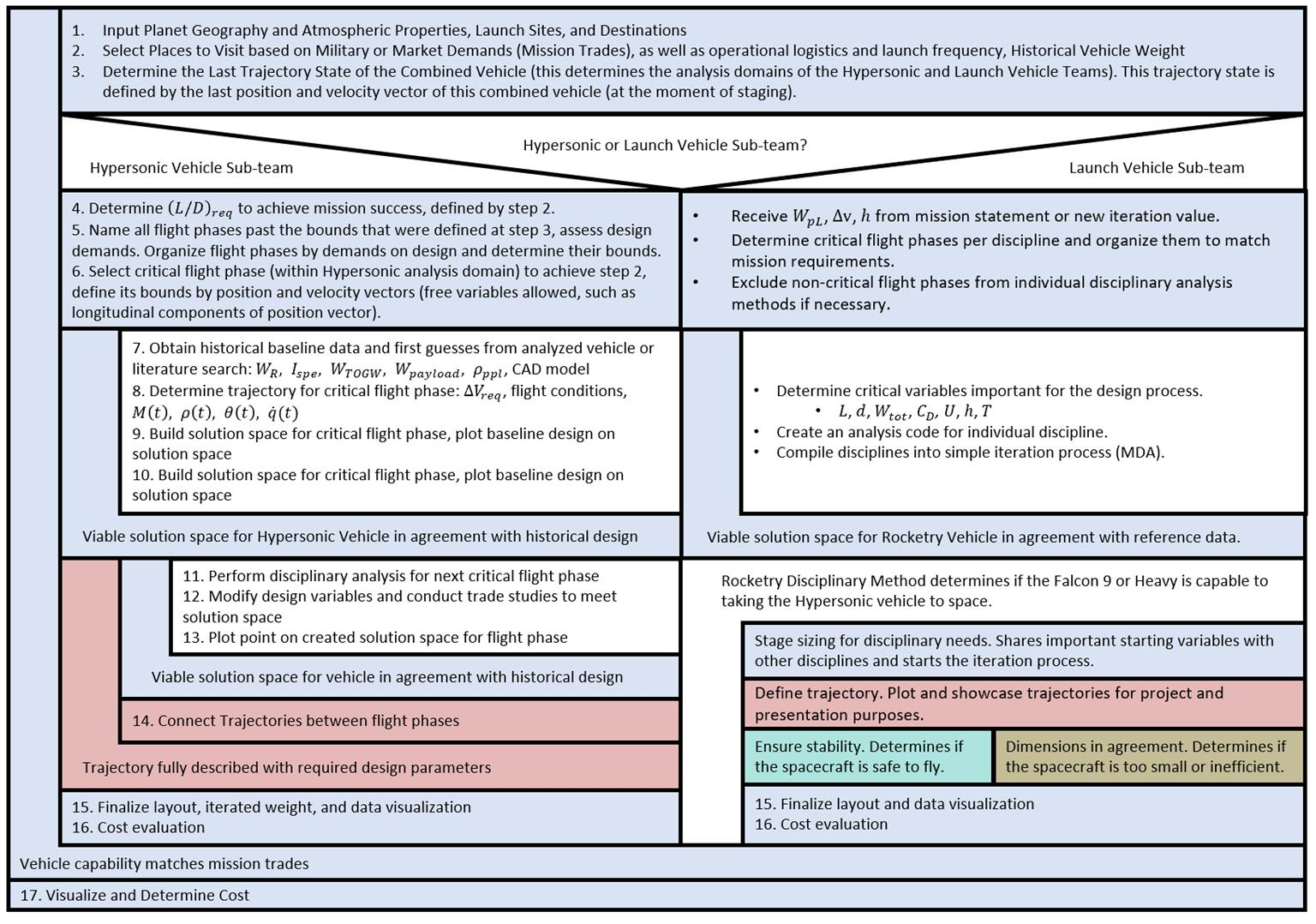
The main objective of the following steps (and upper-hierarchy class MDA in general) is to generalize input variables by evaluating first principles. From here, the team (and user) can easily recognize the fundamental assumptions made during the design process. By implementing a two-tiered MDA system, the class MDA can be more robust to sub-team MDA iterations by containing them inside logical loops.
The first step is to populate the planetary environment in which the vehicle operates and resides in by adding:
- Surface geography (ex: latitude range of mainland Russia or China)
- Key orbits to access (ISS inclination and altitude)
- Planet size and gravitational field (drives cross-range requirements for global access)
- Launch Sites and Landing Zone (Kennedy Space Center at Cape Canaveral, Florida)
- Atmospheric data
This gives us some locations to conduct mission trade studies.
The second step is an input of potential human needs which this vehicle could fulfill. Military as well as civilian market needs are examined (explained in Mission chapter):
- Surprise Reconnaissance in space above military rival for armed readiness and unpredictability
- Logistically favorable transport to a space station
- Point-to-Point transportation
- Escape Trajectory from planetary sphere-of-influence (not feasible without infrastructure on other bodies with atmosphere to complete mission)
The third step is likely to be a major point of iteration between the two teams, so it is worth some discussion. After the two previous mission selection steps, this is where the two teams decide on the last trajectory that both vehicles will share. This is a non-trivial decision since it was found that neither the Space X Falcon 9 B5 nor the historical Titan launch systems could bring any of the Model 176 stages to LEO orbit. For this reason, the shared trajectory will most-likely be suborbital. This will need to be iterated upon to reverse engineer the trajectory that the Model 176 would have taken.
The agreed upon combined vehicle trajectory reaches a ballistic sub-orbit at an apogee of 200 km from the launch pad. The apogee of this sort of orbit is supported as the stable altitude for an orbit which decays slowly enough to allow for orbital operations to take place (as well as the boost circularization maneuver). The following plot shows the relationship between orbit altitude and length of time for a stable orbit before the small atmospheric drag will bring it back down to Earth [34].
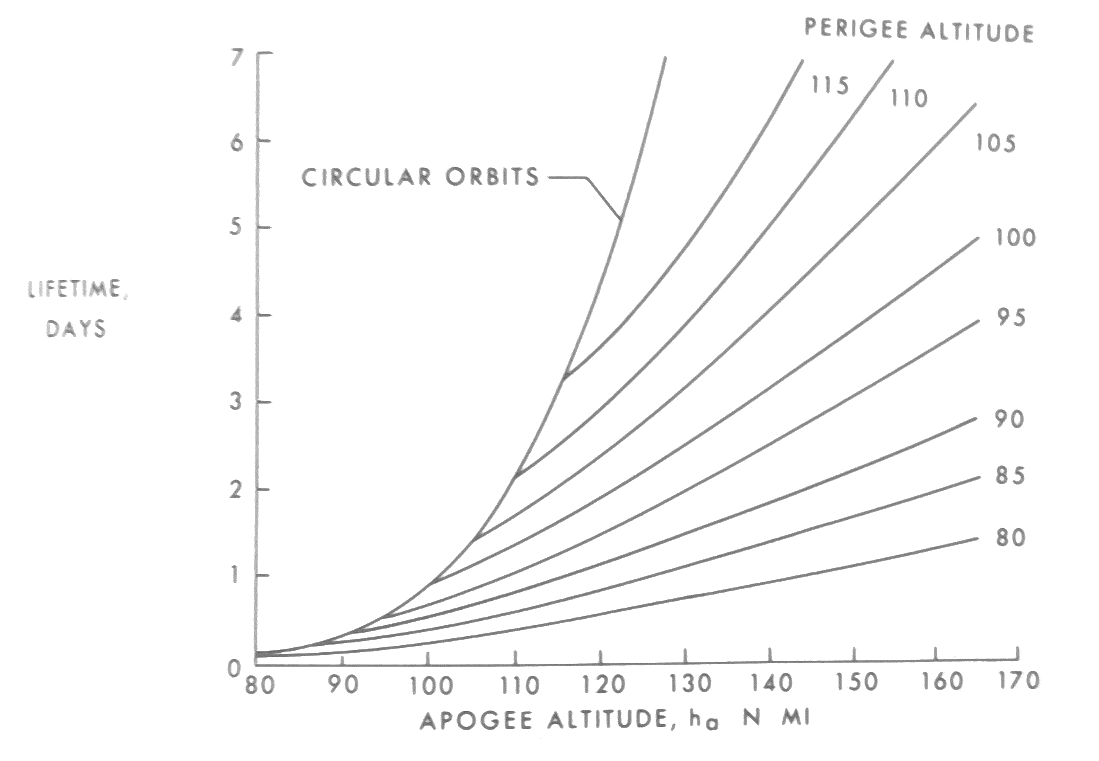
From here, we at least know that the starting point is to determine the domains of both groups: to have the combined vehicle achieve a certain state, as defined by position and velocity in an earth-fixed system. This can be user defined in the synthesis code. The hypersonic vehicle is then expected to circularize this sub-orbit. Any failure to meet mission requirements calls for a re-negotiation of flight domains between the sub-teams.
For the next step, the required lift-to-drag ratio is determined from mission requirements. This will guide the decisions for cross-range capability and inclination change maneuvers. The flight phases for both sub-teams are determined and are explained as they relate to the disciplines in the first section of this chapter as part of the derivation of this MDA. The design-critical flight phase is then selected to be the main test run for the multi-disciplinary approach. The selection criteria involve physical strain on the structure, disciplines required, and unique mission relevance.
Before officially beginning disciplinary analysis, some historical variables are given as part of the project introduction, and they are input here. A CAD Model is also constructed from the historical vehicle.
The multi-disciplinary analysis for both sub-teams is featured in the next two sections.
There are two regions for sub-team multi-disciplinary analysis. As previously stated, the hope is that most iterations were hammered out in the first loop before continuing with into the larger loop which iterates the same process as the first loop, but by connecting the boundary conditions of the trajectories. For this reason, performance is the only other discipline other than synthesis visible on the hypersonic vehicle side of the class MDA.
DMDA for Hypersonic Vehicle
The first version of the Hypersonic Vehicle sub-team’s MDA begins with the design-critical flight phase: hypersonic plane-change maneuver. These are characterized by hypersonic thermal loading and high dynamic pressure loading, respectively. For descent, the idea is that we start with a conservative performance trajectory from a heavier vehicle. The loads are calculated for this trajectory based on initial hypersonic lifting body geometry. Disciplines work to produce a load case for structures in the effort to replicate this conservative trajectory from performance. This load case with thermal and dynamic pressure loads will be used to find a minimum weight design from the structure and CAD disciplines’ selection of materials, structure, and geometry. The minimum weight design is then iterated back to performance to generate a more advantageous trajectory.
From this, the author has developed the following preliminary MDA which could be generalized to each flight phase:
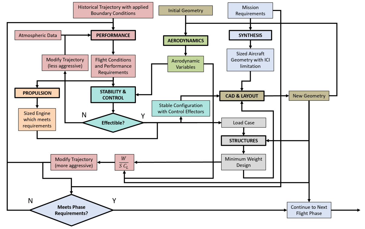
The above MDA is not complete but is rather an expression of the brainstorming process for each phase. This is converted into something more procedural in the time domain, going from top to bottom, as was demonstrated by the class MDA in the previous section. This sub-team MDA will represent the disciplinary analysis introduced as loops in the class MDA.
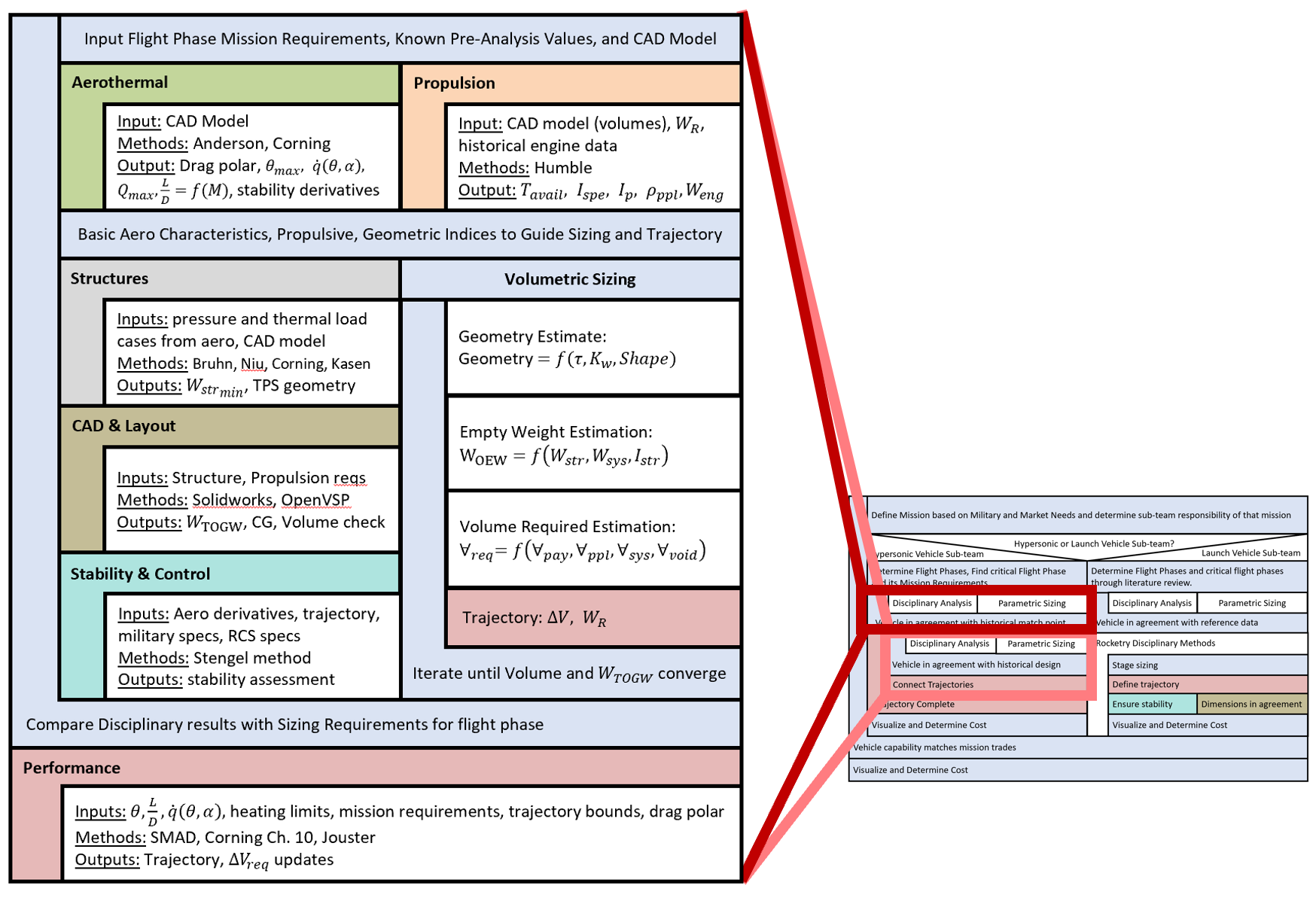
The disciplinary analysis draws from the data found in the previous steps. Additionally, the aerothermal and propulsion disciplines provide initial data for sizing the vehicle. They take disciplinary literature review and the CAD model to develop outputs for the structural aerothermal load case. The TPS is developed by structures in parallel with the sizing methodology. CAD then takes the structural weight and design to develop the total weight of the vehicle, center of gravity location, and volume distribution to set the stage for the stability & control discipline to assess stability for all flight regimes and flight phases based on methods found from literature search.
The parallel sizing methodology iterates until convergence with the historical design given aerodynamic parameters, mission, and new integrated structural and propulsive design. Performance does a trajectory and weight ratio check based on the new design. When sizing is complete, the results are compared to the disciplinary values. If they don’t match, the initial assumptions based on geometry and literature research are re-evaluated. When there is discipline agreement with the solution space, performance builds the trajectory for the analyzed flight phase. After this MDA is complete, the loop highlighted in red situated in the class MDA is complete. The design may now proceed to the next step found at the upper hierarchy level.
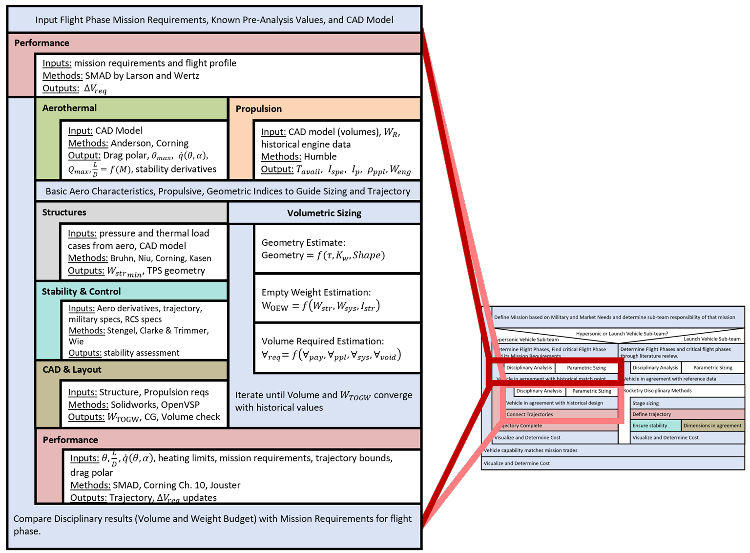
After a flow diagram developed by the Synthesis lead (R. Jain), the author decided to reconfigure the hypersonic sub-team MDA to more closely match it, since it seemed more straightforward and made more sense to the synthesis team. This sort of iteration is expected, especially in this for flexible inner loop. However, it is important to note that this sort of iteration can be done within the existing framework of the larger class MDA, which has the benefit of removing a subconscious resistance to change do to its potential negative effects on the class workflow.
Performance was shifted to be the interpreter of the mission requirements to develop a flight profile for propulsion and aerodynamics. The following disciplinary analysis was adjusted to conclude with the CAD and layout discipline to provide a basis for checking the volume and weight budget.
EMDA for Launch Team
The preliminary sub-team MDA made by the launch sub-team’s chief for the launch team is displayed. This was also later iterated to fit the class MDA.
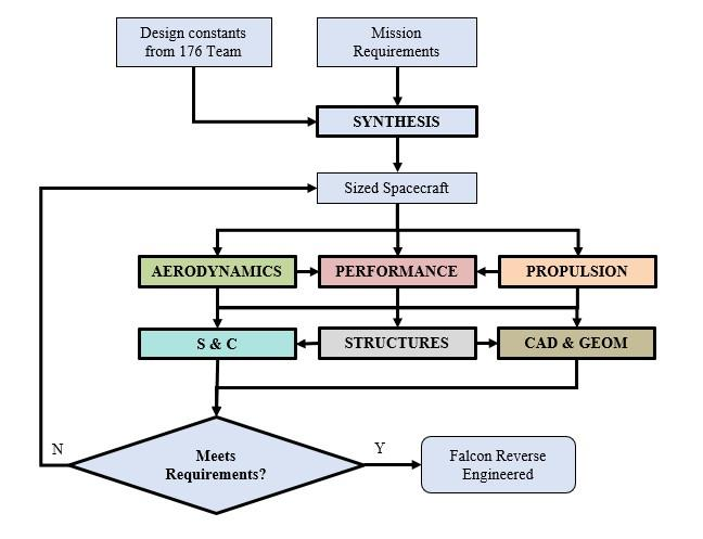
The latest iteration of the Launch team MDA is shown below. There is one main logical loop in the class MDA where this analysis resides in.
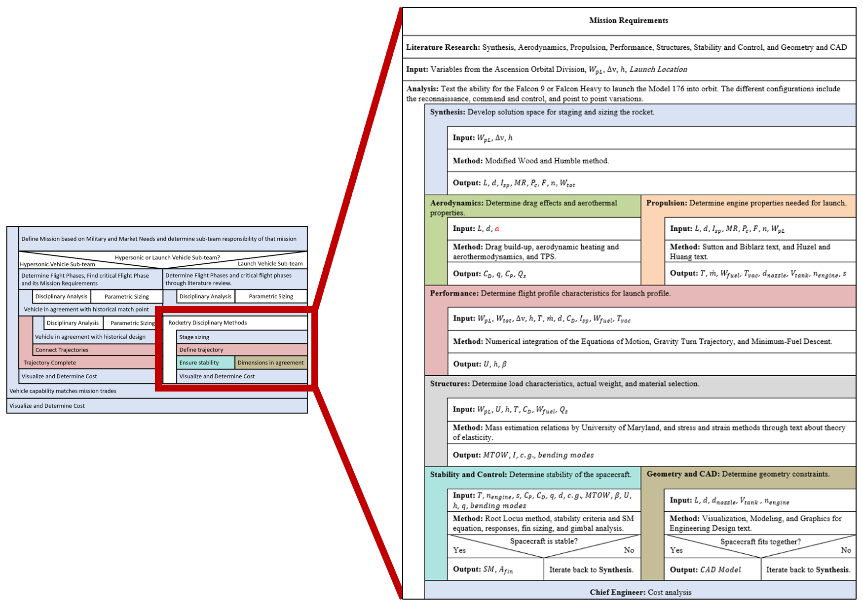
FIDA for Hypersonic Vehicle Disciplines
The disciplines have made a first attempt at their individual disciplinary analysis (IDA), which will be used to finalize the multi-disciplinary analysis. They have all been converted to Nassi-Schneiderman format to reflect the team’s progress on methodology development.
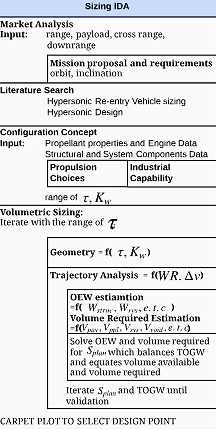
Synthesis IDA [29]:
Performance IDA:
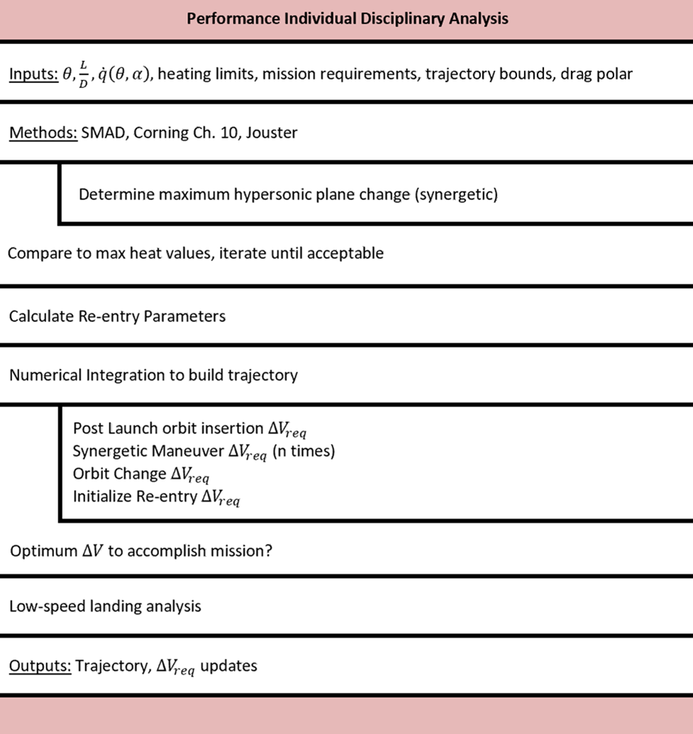
The IDA for performance differs from the other disciplines in that it is organized by a sequence of flight phases. This is due to the fact that a large role of performance is to stitch together all the trajectories into one, thus fulfilling the outer loop requirement found in the class MDA.
Aerodynamics IDA:
Propulsion IDA:
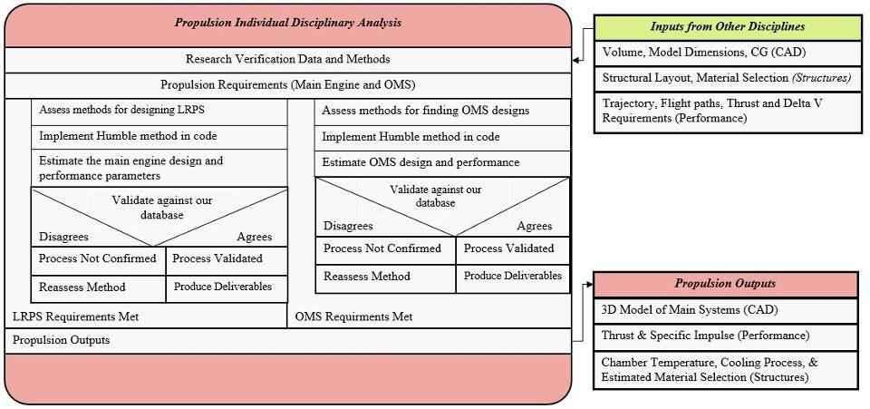
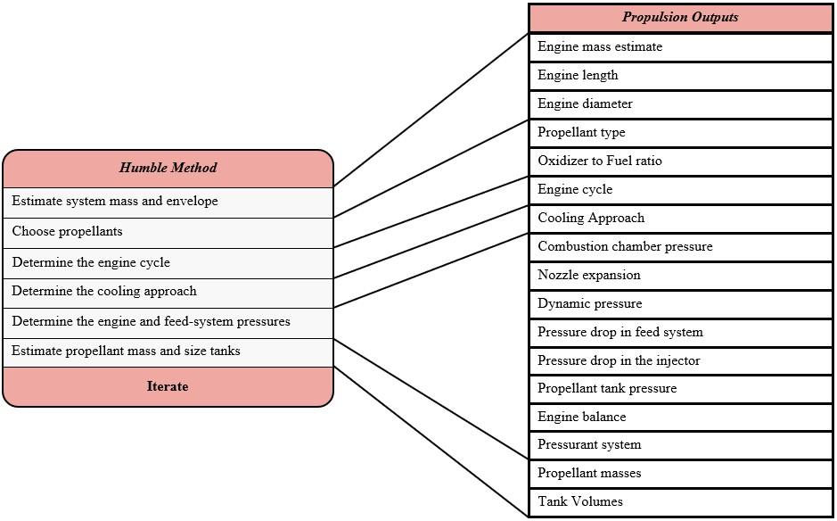
Propulsion methodology expansion on the Humble Method:
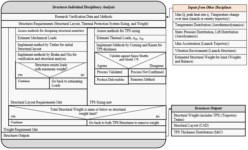
Structures IDA:
Stability and Control IDA:
CAD IDA:
Spotted an error, or want to reply? Email me: leonardo.pinero42 [at] gmail [dot] com